


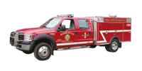
Brush Truck


Ford Cab & Chassis
Unit is to be installed on a Ford F550, Crew Cab, 4 x 4.
- Front Axle : 7,000 pounds
- Rear Axle : 13,500 pounds
- Heavy Service Suspension Package
- Additional springs to rear main springs
- Heavy duty front springs
- Heavy duty, double acting front and rear shock absorbers
The power train should consist of the following :
- Ford Power stroke V8, 6.0 L Turbo Diesel Motor
- Automatic transmission
- Part-time four wheel drive
- Ambulance package (Includes: Dual 130 Amp alternators, full function auxiliary idle control kit, air conditioning.)
Interior requirements are as follows (XL package) :
- Black floor mats in place of carpeting
- Upfitter switches (4)
- 2-Heavy duty vinyl bucket seats instead of bench seats
- Air conditioning with high output fresh air heater
- Am/Fm Stereo with digital clock
Exterior requirements are as follows (XL Décor package):
- The cab will be painted Ford Fire Red
- Trailer tow package
- Chromed front bumper
- New design front lights
- Argent grill
- Primed grey wheels.
- Dual front tow hooks
- Mirrors, manually telescoping trailer tow with manual glass and two-way fold
- The tires should be a maximum traction mud / snow tire
- The wheel base should be 176” wheelbase / 60” cab to axle
- Chromed tubular steps, one (1) each side of the cab
Major Standard Features :
- Two (2) front tow hooks
- 7-pin wiring trailer harness
- Axle – Front Monobeam with coil spring suspension
- Battery – 750 CCA 78-AH
- Brakes – Anti-lock System (ABS)
- Dual instruments panel mounted cupholders
- Engine hour meter
- Exterior cargo light – Back of cab
- Front and rear stabilizer bars
- Fuel tank – 40 gallon capacity
- Grab handles – Driver and front passenger
- Manual transfer case and hubs (4 x 4)
- Power steering
- Roof clearance lights
- Scuff plates
- Solar tinted glass
- Steering damper
- Windshield wipers – interval
Safety & Security :
- Airbag – Driver and front passenger
- Belt-Minder safety belt reminder
- BlockerBeam – includes valance air dam
- Passenger airbag deactivation switch
Outer wheel inserts
The front and rear wheels shall be dressed with polished, stainless steel wheel liners, hub covers and lug nut covers. Brand to be Realwheels.
Lettering & Stripping
The finished apparatus shall be lettered to match the existing apparatus, the door logo shall be provided by the Fire Department. The Apparatus number shall be applied to each side of the chassis hood. 4” Reflective 3M stripping shall be applied on the Cab & the truck bed as per NFPA.
Winch
There shall be a 9500 lbs. WARN Removable electric winch installed with 125’ (38 m) of 5/16’’ cable. There shall be a winch receiver installed at the front and rear of the Brush Truck. A remote with 25’ of cable shall be supplied.
In addition, this system includes a chromed grille/brush guard which wraps to the outside of the headlights
A rear mounted Class IV trailer hitch shall be securely attached to the chassis frame and shall include the 7pins electric plug.
Polybody
The body shall consist of a left and right side module with doors. In addition, there shall be a formed metal header panel, threshold panel and floor panel. These components shall be assembled to form the modular body and shall be supported by a steel subframe weldment. All components of the body shall be bolted together to allow for easy replacement. Threaded inserts shall be installed into all blind mounting holes. All other fasteners shall be stainless steel.
Material
The material used to construct the body side modules and doors shall be extruded copolymer polypropylene made from Amoco 3045 AccTufTM resin.
This material shall be referred to throughout the rest of this specification as «3045 polypropylene».
Street side body module
There shall be a multi-compartment body module constructed from ½» 3045 polypropylene provided to form 3 compartments on the street side of the body. There shall be a single door compartment ahead of the rear wheels, a single door compartment over the rear wheels and a single door compartment behind the rear wheels. A utility style radiuses wheel opening shall be provided. Flush fuel filler doors shall be provided as required with removable inner pockets .Compartment dimensions shall be as follows
Compartment ahead rear wheels : 35” width, 19” depth, 45” height
Compartment behind rear wheels : 35” width, 19” depth, 45” height
Compartment over rear wheel : 47” widht, 25” depth, 21” height
Curb side body module
There shall be a multi-compartment body module constructed from ½» 3045 polypropylene provided to form 3 compartments on the curb side of the body. There shall be a single door compartment ahead of the rear wheels, a single door compartment over the rear wheels and a single door compartment behind the rear wheels. A utility style radiuses wheel opening shall be to provided. Compartment dimensions shall be as follows
Compartment ahead rear wheels : 35” width, 19” depth, 45” height
Compartment behind rear wheels : 35” width, 19” depth, 45” height
Compartment over rear wheel : 47” widht, 25” depth, 21” height
Transverse compartment
Inside Tranverse compartment will communicate the two compartment ahead rear wheels. Compartment will have approximate dimension of 20-1/2” x 96” x 29”.
Upper section of the body
Street side shall have two (2) x pre-connected hose tray (jumplines) with 90 deg. Swivel connected directly to the pump manifold. Protective net will be installed. Curb side shall have one (1) hose storage compartment to hold 1-3/4” x 450’ of hose. Protective net will be installed.
At the front of the body, one (1) dunage compartment (approx.: 21” x 96” x 10”)
Upper section will be made from .125” high bright aluminum diamond plate.
Rear compartment
One (1), integrated to the polybody, compartment approximately 5’’ high x 24’’ wide x 112’’ long for suction hose storage and folding ladders or pike poles. A flip down horizontally hinges door is furnished at the rear. The interior compartments is made from polished 3003-H14 alloy smooth plate. Steel frame underneath Drop-In-Unit shall not be acceptable
Compartment doors
Each compartment shall have a single box-pan style flush door constructed from 3045 polypropylene. The latch mechanism shall consist a die cast metal locking paddle-type door handle with two (2) rotary automotive type latches and two (2) stainless steel adjustable striker pins. Removable panels in the back of the door panel shall allow access to the concealed latch mechanism. There shall be two fully adjustable concealed stainless steel hinges with a ¼» pin which shall be fastened to both the door and the compartment. A hollow neoprene automotive bulb type door gasket shall provide the seal for the door against the compartment. The horizontally hinged doors shall be retained by two gas shock lifter per door.
Upper roof area & extending down over side approx. 2” to the compartment doors and then forming a drip rail above doors.
Compartment ventilation
All compartments shall be ventilated through an integrated positive pressure vent system allowing for movement of air between compartments. Vent outlet at the front of the side compartment modules shall provide a water resistant entry and exit for air.
Subframe
A steel subframe weldment shall be fabricated from tubing and formed sheet metal to provide a mounting platform for the body side modules and the floor. There shall be outriggers extending out and down from the sub frame to provide support to the side pack floors. There shall be four (4) outriggers supporting each side module. There shall be common attachment points along the length of the sub frame for mounting it to the truck chassis. The finish on the subframe shall be a semi-flat black urethane enamel.
Body header panel
A formed .125» high bright aluminum diamond plate panel shall be provided at the front of the body and shall extend the full width and height of the body to provide full frontal protection to the body side modules. The header panel shall be fastened to both body side modules. Louvers shall be stamped into each side of this header panel to provide air to vent the compartments. A second inner reinforcement panel shall be formed behind the header panel at the front of the cargo area. It shall have three (3) integral reinforcing ribs to provide maximum strength.
Body threshold panel
A formed .125» high bright aluminum diamond plate panel shall be provided at the rear of the body and shall incorporate a formed backsplash lip under the cargo floor. It shall extend across the lower width of the body under the cargo floor area. This panel shall be fastened to both body side modules.
Cargo floor
The floor of the cargo area shall be formed from .125» high bright aluminium diamond plate and shall extend the full width between the body side modules. The floor shall incorporate formed vertical flanges on each side, which are fastened to the body side modules. All compartment floors will be covered with Plastic Tiles.
Adjustable shelf tracking
Each compartment shall have four (4) aluminum tracks fastened to the interior sidewalls to provide an adjustable mounting surface for shelving.
Adjustable shelving
There shall be adjustable shelving formed from .125» thick smooth aluminum sheet. Each shelf shall be fastened to the tracking using four (4) adjustable shelf clips and stainless steel hardware.
Compartment Location Number of shelves
To be determined w / Fire Dept. 4
Sliding Trays
Two (2) sliding trays with 200# automotive slides and aluminium pan. Location to be determined w / Fire Dept. Gas shock will be installed to keep a positive tension when sliding tray is opened.
Bumper
A full width bumper shall be provided at the rear of the body formed from 12 gauges steel. Steel brackets shall be incorporated to attach the bumper to the vehicle chassis. A aluminum grip strut with radius corners shall be fastened to the steel brackets. Protection between steel and aluminum will be added.
Others
Two (2) pair of tow hooks to be installed, one (1) pair in the lower front of the chassis (Supplied by Ford), and one (1) pair in the rear of the body above the rear compartment.
Two (2) Anti-Slip grab rail on top side compartments. Grab rail shall be extruded polished aluminum (Bright Anodized) tube with rubber inserts providing maximum gripping ability.
A bright, anodized rubber aluminum rub rail extrusion shall be bolted on both sides of the body below the compartment to protect the body from minor scrapes.
Electrical components
A 12 volt electrical system is supply. The built in emergency light switch panel have a master switch plus individual switches for selective control. The switch panel is located in the cab on the driver’s side to allow for easy access. The switches on the dashboard is lighted rocker type.
The wiring is secured in place, readily accessible and protected against heat, water and physical damage.
All wiring will be run in heat and moisture resistant plastic convoluted split loom.
Grommets will be used where conductors or loom pass through metal.
Power control relays and solenoids shall have a direct current rating of 125 percent of the maximum current for which the circuit is protected.
Conductor insulation will conform to S.A.E. requirements. All circuit are protected by automatic reset circuit breakers.
All wiring furnished will conform to the national Electric Code.
All circuits will be wired in conformance with S.A.E. J1292, Automobile wiring standard.
All wiring will be function worded schematically.
A set (2) of electric diagram will be remit upon delivery.
One (1) back-up alarm that meets the type D (87 dba) requirements of SAEJ994 shall be provided at the rear of the apparatus. It will activate when the transmission is placed in reverse.
DOT lighting :
Lighting and reflectors shall be provided that comply with federal motor vehicle safety standard FMVSS-108. This shall include a 7” x 8” rectangular red stop/tail/turn light and a 7» x 8» rectangular back up light on the rear of each body side module. These lights shall be mounted to the body with appropriate gasketing. The street side module shall have a license plate light and mounting provisions for license plate under it. Note : on bodies over 80» wide, a red triple clearance light cluster shall be provided in the lower center of the rear panel. All wiring shall be in split convoluted loom to form a harness. An aluminum protection cover shall be provided over the harnesses at the inside rear body panel to guard against damaging the harness due to shifting cargo in the compartments.
Compartment lighting
Each compartment shall have a single filament light mounted in the upper portion on the inside panel. The light shall have a defused lens to provide maximum illumination. The lights shall be controlled by a single switch located in the cab with an «ON» indicator. All wiring shall be properly sized, GXL, copper stranded, function coded and concealed in a split convoluted loom harness and routed through the body. Automotive type snap in loom clips shall hold harnesses securely in place.
Ground lights
Six (6) ground lights shall be installed at the entry to the cab (1 each side) at the side of the body (1 each side) and at the rear corner of the apparatus, one each side. These ground lights will be illuminated at any time the chassis parking brake is activated. Lights to be Ziamatic, model # GLB/L.
Drop-In Unit lighting
There shall be a Weldon Series 2000 flat backlight installed in the pump area to provide lighting for the pump operator.
There shall be a switch on the pump operator’s panel installed to enable the rear backup lights as well as a pump area light to turn on without the vehicle being in reverse gear.
Emergency lighting
One (1) Lightbar Whelen, Ultra Freedom model.
- NFPA Super LED
- 2 x Alley Light
- 2 x Front Take Down
Mounted on front Ford grill, Two (2) Whelen 4E series Led, red, each with a chrome flange.
Mounted each side of the chassis, Two (2) Whelen 4E series Led, red, one each side, each with a chrome flange.
Mounted each side of the body, Two (2) Whelen 4E series Led, red, one each side, each with a chrome flange.
Mounted in the rear lower section of the body Two (2) Whelen 4E series Led, red, each with a chrome flange.
One (1) Code #711 wig-wag system will be installed with a control switch on the console.
Siren & Speaker
One (1) Whelen, 100 watts electronic siren amplifier and switch control center to be provided and installed. Model to be #295HFSA1.
One (1) Whelen 100 watt speaker, model #SA314Pwith black finish, to be provided and mounted on the front bumper.
Scene Lights
Four (4) Scene Lights, Two (2) 150 Watts telescoping 12v Scene Lights mounted at the front of the body and two (2) 150 Watts telescoping 12v Scene Lights mounted at the rear of the body. The light shall be single head design. Lights will increase visibility around the apparatus during night or light operations.
Lights to be High Intensity Discharge (HID). Unlike the halogen incandescent bulbs, the HID bulb does not contain a filament. Instead, it creates light from an electrical discharge between two electrodes. This technology provides a brighter and crisper white light that is superior to halogen source because it most resembles natural daylight and is very efficient.
Model is to be Fire Research Optimum lamp heads with side mount, push up telescopic pole, #OPA512-H15. A switchbox is provided underneath each lamp head. Scene lights shall be wired.
Reels
Two (2) Hannay Reels to be installed in the left front compartment for Hurst Tools.
Console
One CET aluminum consol installed between seats with lighted rocker switch. All switches shall be appropriately identified by panel mounted legends.
The consol will have an area to accommodate department map books, clipboards etc..
The console also have an area for radio head installation.
A Hand-Held / Tripod Spot Lamp installed on the console. Features, 1,500,000 C.P. for high intensity output ; Hand held base opens to become tripod base for a work light ; H3, 100 watt halogen bulb ; 20 ft. Power cord.
Map Light, 12” gooseneck Halogen, Havis Shield, model C-MAP-S, side mounted on the cab console.
There shall be a warning light installed in the chassis cab to illuminate and flash when a compartment door has been opened.
Controls and switches that are expected to be operated by the driver while the apparatus is in motion shall be within convenient reach for the driver.
Paint
Preparation and painting of the PolyBody shall be done within accepted industry standards.
The commercial body paint will have to match the Ford Red chassis colour.
The PolyBody exterior shall be red with contrasting reflective striping in accordance with NFPA. Details of 4” stripping to be confirmed with purchaser at appropriate time.
The interior of the body compartments shall be left in their natural colour of white.
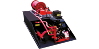
CET Fire Pumps Mfg Drop-In-Unit
Tank
The UPF Defender III series shall be constructed of 1/2" thick polypropylene sheet stock with AccTuf™ resin. The material shall be of a certified, high quality, non-corrosive, stress relieved thermo plastic, black in color with a textured finish, and UV stabilized for maximum protection. The skid type booster tank shall be of a standard configuration and shall be so designed to have complete modular slide in capability. All joints and seams are to be fully nitrogen welded and electronically tested for maximum strength. The unit shall incorporate transverse partitions manufactured for 3/8" UPF PT2E polypropylene which shall interlock with a series of longitudinal partitions constructed of 1/2" PT2E polypropylene. All swash partitions shall be so designed to allow for maximum water and air flow between compartments and are fully welded to each other as well as to the inside of the tank. The passenger side rear wall of the tank shall have a standard built in sight gauge 2" in width, and 70% transparent.
Fill tower and tank cover
The tank shall be equipped with a combination vent/overflow and manual fill tower. The fill tower shall be an 8" round by 6" high with a molded drop-on type cover. The cover shall be fastened to the tower with a teather to prevent loss. The tower shall be located in the right rear corner of the tank. There shall be a vent / overflow installed inside and to the extreme rear of the tower approximately 2" down from the top. This vent / overflow shall be of a standard schedule 40 polypropylene pipe with minimum ID of 3". The vent / overflow shall be piped internally toward the front and exit out the front tank wall with a 1" extension past the front tank wall.
The tank cover shall be constructed of 1/2" thick PT2E polypropylene, black in color, UV stabilized, and incorporate an exclusive self locking design. The cover shall incorporate (4) 2" polypropylene for hold-down and lifting provisions. These dowels shall be tapered for ½" -13 threads to accommodate a lifting eye with a minimum security factor of 3 to 1. These dowel shall be welded into the transverse baffles, and will assist in minimizing cover flex during normal operation
Tank Capacity
The tank shall have a capacity of 300 U.S. gallons of water. The tank shall be covered by the UPF ALL OUT No Fault Life Time Warranty.
Sump
The floor of the tank shall be manufactured from 3/4" PT2E polypropylene. There shall be one (1) sump as standard per tank. The sump shall be integral to the tank floor and be a minimum of 5/8" deep recessed into the floor. The sump shall not be visible from or protrude through the bottom of the tank.
Tank Outlets
There shall be two standard tank outlets located in the same vertical plane on the driver side rear wall of the tank. One (1) 3" female NPT tank to pump suction fitting and one (1) 1" female NPT tank fill fitting with flow deflector
Tank Mounting Blocks
The cover shall incorporate two (2) booster reel mounting blocks that shall be to accommodate two (2) each sliding nut fasteners. These mounting blocks shall be welded to the covers running from the rear edge of the tank forward.
Lifting Eyes
There shall be two removable lifting eyes to be included at the top of the tank.
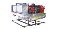
Skid Base
There shall be a full width skid base manufactured of 3/4" PT2E polypropylene welded to the tank. This base shall be 48" wide by 96" long and shall extend 34" past the tank in the rear to allow for pump mounting. The pump mounting area shall be supported by ½" PT2E polypropylene gussets 15" high by 32" long. The gussets shall be equipped with 2" holes to assist in lifting the unit. The mounts shall allow for the truck to be secured directly to a truck bed without the need for any skid frame work underneath.
Mounting
The Drop-In-Unit shall be mounted in a manner that allows access to the engine, pump, and auxiliary systems for routine maintenance. The Drop-In-Unit shall not be welded or otherwise permanently secured to other components.
Pump, PFP-18hpHND-MR
The pump shall be a CET PFP-18hpHND-MR single stage centrifugal pump, bolted directly to the engine, with a 2.5" NPT suction inlet, and a 1.5" NPT discharge outlet. The volute and pump head shall be a lightweight, high strength, seawater resistant, aluminum alloy. The impeller shall be a bronze enclosed type for maximum efficiency, fully machined and balanced. The engine crankshaft shall serve as the pump shaft, with the impeller mounted directly on the crankshaft. The shaft seal shall be self-adjusting, self lubricating, mechanical type. The pump shall be equipped with a brass drain cock.
The pump shall be equipped with an exhaust venturi type primer capable of 20' lift for fast positive priming. The control for the primer shall be capable of being operated by a person operating controls at the primary pump operator’s position.
The pump shall be capable of a maximum discharge volume of 250 g.p.m. at 50 psi, and a maximum discharge pressure of 200 psi while pumping 25 g.p.m. In the center of the performance curve, the pump shall be capable of pumping 160 g.p.m. at 100 psi and 100 g.p.m. at 150 psi.
Engine
The pump shall be driven by a 2 cylinder, gasoline engine powered, 18 horsepower V-twin overhead valve engine. The engine shall be air cooled, 12 volt electric start and recoil rope starter as a back up system. The engine shall be fuelled from a separate 6 gallon gas tank. The engine shall be connected to the main battery of the truck.
Pump Controls
A control panel shall be supplied and installed on the pump. The controls shall consist of a start button, 2.5" diameter discharge pressure gauge and one work light. The Throttle lever, choke control and a low oil level shut down are part of the engine configuration.
Centreline of any control shall be no more than 72 in. vertically above the ground or platform that is designed to serve as the operator’s standing position.
Scotty Foam System
There shall be a Scotty model 4071 around the pump foam eductor / mixer installed integral to the pump. The eductor shall be plumbed from the foam cell with ½" flexible reinforced tubing to throughout the eductor to a suction fitting on the pump impeller housing. The eductor shall be calibrated to educt foam concentrate at variable percentage into a discharge manifold flowing 15, 30, 50 and 70 gal. per min. The eductor shall be capable of a discharge of a 1% foam solution at specified flows.
10 gallon Drop-in integrated foam cell will be included. A label that reads “Foam” shall be placed at any foam concentrate tank fill opening.
Booster Reel
A Hannay 12v electric rewind booster reel capable of handling 200' of 1" diameter booster hose shall be supplied and installed on the tank top pre-connected to the main manifold. The reel shall have a push button rewind control and a backup geared crank rewind handle. The reel shall be equipped with a 1" NPT 90 degree swivel inlet, and a 1" NST outlet riser. The reels discs and drum shall be manufactured of polished aluminum and be silver in color.
Two high mounted roller and spool assemblies shall be furnished and installed on the booster reel. The rollers shall be located one on each side of the reel to facilitate deployment of the hose to either side of the vehicle.
The booster reel shall be equipped with 200' of 1" "Neidner ReelTex" fabric covered booster hose. The hose shall have a working pressure of 600 psi and be furnished with 1" NST lightweight couplings. The weight of the hose shall not exceed 23 lbs per 100' coupled.
Plumbing and Valves
Suction Piping
All piping shall be Stainless steel piping, painted red. The suction piping shall consist of a 2.5" tank to pump line with a 2.5" flexible rubber hump hose to minimize flex and vibration between the pump and the tank. RIGID PIPING SHALL NOT BE ACCEPTABLE. Between the tank and the pump there shall be a 2.0" Akron self-locking swingout valve, model # 8820 and a R1 handle. This valve shall remain open to pump from the tank. This pipe shall have a tee into the suction side of the pump, and shall continue to the rear of the truck for overboard suction.
The overboard suction connection shall have a 2.0" Akron self-locking swingout valve, model # 8820 and a R1 handle and 2.5" NST male adapter w/cap with retaining cable. To draft, the tank to pump valve shall be closed, a suction hose connected to the overboard suction connection and placed in a static water supply, and the primer activated.
Discharge Piping
All piping shall be Stainless steel piping or high pressure flexible hose. A 2.5" X 2.5" square steel manifold shall be piped directly to the discharge outlet of the pump. Attached to this discharge manifold, by means of welded steel pipe nipples, shall be all the discharge valves. All piping shall be painted red to match the pump.
All valves larger than 1" shall be Akron self-locking swingout valves, with R1 style handles for ease of operation and maintenance. Any valve 1" or smaller shall be standard plumbing style valves.
Tank Fill
There shall be a 1" valve piped from the discharge manifold as a means for refilling the tank. The valve shall be an industrial, quarter turn valve handle and 1" NPT threads, and shall be connected to the tank fill port by 1" high pressure flexible hose.
Discharge to Booster Reel
There shall be a 1" valve piped from the discharge manifold to the booster reel. The valve shall be an industrial, quarter turn valve handle and 1" NPT threads, and shall be connected to the reel by 1" high pressure flexible hose.
1.5" Discharge To Rear
There shall be one 1.5" valve piped from the discharge manifold to the rear of the truck for connection of forestry hose. The valve shall be an Akron 8815, quarter turn self-locking swingout valve with a R1 handle and 1" NST threads. The valve shall be furnished with a 1" NST cap and chain.
2.5" Discharge to Rear
There shall be one 2.5" valve piped from the discharge manifold to the rear of the truck bed. The valve shall be an Akron 8820, self-locking swingout valves with a R1 handle and 2.5" NST threads. The valve shall be furnished with a 2.5" cap and chain.
Garden Hose Discharge
There shall be a standard garden hose valve piped from the manifold.
1.5" Discharge to Preconnected Hosebed
There shall be a 1.5" valve piped from the discharge manifold to the hosebed. The valve shall be an Akron 8815, quarter turn self-locking swingout valve with a R1 handle and be connected to the hosebed by high pressure flexible plumbing. There shall be a 1.5" crosslay swivel located in the hosebed.
1" Tank Drain
There shall be a 1" valve piped from the tank drain fitting to the rear of the truck bed. The valve shall be an industrial, quarter turn valve with a handle and 1" NPT female threads.
Approximate weight of the Drop-In-Unit including hose reel(s) and full of water and other liquids shall be given before production.
The Drop-In-Unit electricity will be connected directly to the main battery of the chassis
Apparatus built accordingly to NFPA 1906 & DOT Compliant
Testing
The pump shall be tested after the pump and all its associated piping and equipment have been installed on the fire apparatus. The tests shall be conducted at the manufacturer’s approved facility.
The testing shall include at least the pumping tests, the priming device test, the vacuum test. The water tank-to-pump flow teat, and the piping integrity test.
Manufacturer’s discretion
Materials, parts, or procedures used are subject to change at manufacturer's discretion at any time to provide equal or better products.
